Wiring Diagram Receiver And Emitter In A Plc

Implementation Of The Microcontroller For A Transmitter And B

Block Diagram Of The Proposed Plc For A Transmitter And B

A The Plc System Master Slave B Implementation Of The
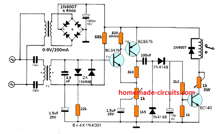
Remote Control Using Mains Power Line Communication Homemade

Circuit Diagram For Ir Based Audio Transmitter And Receiver

Pin On متنوعات

The sensor has two outputs that may be tied into a programmable logic controller input of the sinking type.
Wiring diagram receiver and emitter in a plc. The below figure is an overview of one discrete digital on off circuit showing the entire process from the power supply through the sensor and on to the plc. Just like on the diagram we start with the stop push button. 1 888 373 6767 representative in eu. This would mean that the com terminal should be connected to the common or return or side of the power supply not the chassis ground and that the device to control would be between the positive supply and the no terminal.
The lower voltage is then used to supply power to the left and right rails of the ladder below. I m using the siemens tia portal as the plc programming software. A sick wl12 3p2431 photo eye is an excellent example of a basic on off pnp sensor. The sensi tivity is correctly adjusted to the light on operating level at the rated sensing distance and the sensing object is moved along the length and parallel to the slit.
The emitter and the receiver as shown in the figure. The emitter receiver pairs are scanned sequentially one at a time by a very short pulse of infrared light starting from bottom cable end and working up to the end until every beam pair has been scanned. The 1 zone connecting block 4 emitter outs provides a low cost means of connecting xantech ir receivers to one single or dual emitter and a power supply 5 25. Two 16 bit computers in the fi rst emitter pylon and two 16 bit computers in the fi rst receiver pylon control.
Peter mertens managing director banner engineering europe. But you said your proportional solenoid is wired to a 1762 of4 analog output module. Xantech structured wiring products include infrared targets infrared connecting blocks infrared couplers infrared emitters keypad modules infrared remote controls and infrared. The wiring diagram dictates a standard configuration which requires a 24vdc and gnd signals for power.
It will be represented with an examine off bit. Js what you posted is the standard wiring diagram for how to wire a 3 wire signal transmitter with it s own external power supply to a micrologix plc analog input. These look like a normally closed nc contact. Figure 1 a motor controller schematic.
The contacts m will be controlled by the coil m the output of the motor starter goes to a three phase ac motor. Item explanatory diagram meaning through beam sensors emitter receiver retro reflective sensors emitter and receiver. Plc digital signals wiring techniques ina process plant on off control is done through the plc or dcs.
Receiver Pnp Output Wiring Diagram Emitter M12 Wiring Diagram
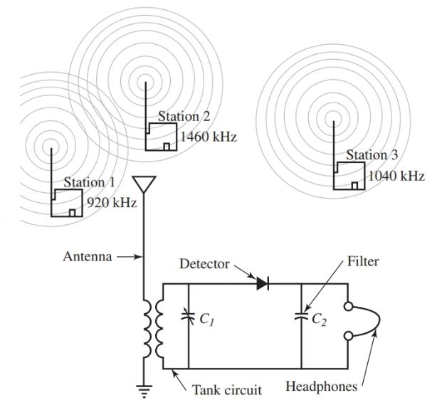
Radio Transmitter And Receiver Working Block Diagram

Plc Timer Instructions Ladder Logic Plc Programming Programming
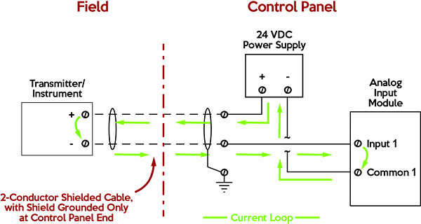
Industrial Communications 4 20 Ma Current Loop Allied

Simple Ir Audio Transmitter And Receiver Circuit With Images

Simple Ir Audio Transmitter And Receiver Circuit With Images

Control Up To 16 Appliances Without Using A Microcontroller

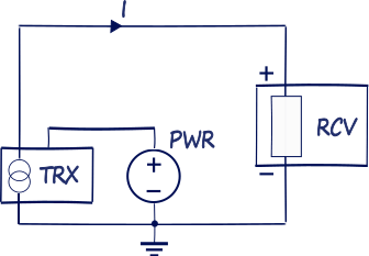
Current Loop Connection Divize Industrial Automation
Nikolay Bozov Industrial Automation And Control

Rf Remote Transmitter Circuit Diagram Circuit Diagram

Control Up To 16 Appliances Without Using A Microcontroller

Usb Fm Transmitter Circuit With Images Fm Transmitters

Zz 5104 Wireless Microphone Circuit Diagram Schematic Wiring
