Voip To Rj11 Wiring Diagram
Rj11 Pinout Informations Forum For Electronics

Rj11 Phone Wiring Wiring Diagram

Vy 1614 Rj45 Rj11 Telephone Jack Wiring Diagram Wiring Diagram
Phone Wiring

Phone And Computer Connection Diagrams Voip Business Support

Zg 4504 Parrot Bluetooth Wiring Diagram Moreover Parrot Ck3100
Rj11 wiring diagram rj11 socket wiring diagram rj11 splitter wiring diagram rj11 wiring diagram every electric arrangement consists of various diverse parts.
Voip to rj11 wiring diagram. Regular telephone wire cat3 and rj11 jacks do not support voip. Most cable nowadays is utp unshielded twisted pair. Cat6 cabling should be used where throughput of greater than 100mbps is desired. Taking a close look at the wiring diagram it appears to follow t568b on the rj45 side.
If your phone jacks pinouts follow usoc this adapter won t work. Cut off the wire right at where you applied the wire stripper. The diagram is shown with the hook clip on the underside. Go about an inch or more in and strip the telephone wire.
Now use the string inside with the wire pairs to pull back cutting further into the wire exposing more. How to wire a phone jack voice or telephone rj 11 thru rj 14 usoc wiring diagram telephone wiring for a phone outlet is typically either 1 2 or 3 pairs 2 4 or 6 conductor. You can still use it with t568a pinouts but line 2 and 3 will be swapped. Phone and computer connection diagrams.
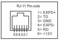
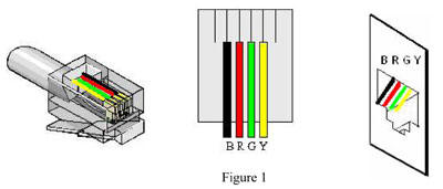
Rj 11 is the standard for most telephones answering machines and fax machines used in north america. Each workstation where you will be installing a voip phone must have category 5 cat5 category 5 enhanced cat5e or category 6 cat6 cabling installed with an ethernet rj45 jack. Figure 1 is the wiring scheme for the plug side of an rj 11 connector. The typical rj 11 connector has six terminals.
Otherwise the structure won t function as it ought to be.

Crimping Rj 45 With A Cat6 Cable Networking

What Is Mobile Voip And Should You Use It With Images Voip

London Business Telephone Systems Ip Voip Pbx Data Network

1 59 Rj11 6p4c Male Plug To 5 Ports 6p2c Female Socket Phone

K Means Advantages Disadvantages With Images Computer

Computer Network Accessories Cosas Para Comprar

Con La Nueva Placa Modular Golmar Nexa Crea Tu Propia
